SMD Reflow Soldering

Sparkfun has a tutorial describing reflow soldering with a skillet. A couple of months after I read this “kruidvat” had a cheap skillet on sale.

If you use the skillet for reflowing PCB’s, don’t use it to prepare food.

What I needed too were tweezers and soldering paste. Good tweezers can be expensive and soldering paste is quite hard to find.

A warning about shopping for soldering paste. The name “soldering paste” can be used to two things : one is “flux paste” which will allow the solder to flow but does not contain any solder itself. The other is a paste or gel containing a tin alloy, flux and a carrier gel. You’ll need the last kind.

I was surprised to find out that DealExtreme, my favorite webshop for cheap stuff has both.

Sku 4711 is a quite usable soldering paste. DealExtreme sells both kinds of soldering paste. Make sure you get the right kind.

Sku 19866 are nice tweezers.

You’ll need some way to get the paste on the pads. I used a syringe to get the paste in a small syringe and used the small syringe to apply the paste.

Air-bubbles or water in the paste cause problems during reflowing.  The water will boil and the air will expand causing the paste to splatter.

It’s messy.

Then I applied the paste.

One thing I did wrong was putting way too much paste in the syringe. The paste is a mixture of tin powder, flux and a gel. The powder separates from the gel in the syringe and if you put too much paste in the syringe you’ll end up with clogged syringe.

I placed the SMD parts in the paste.
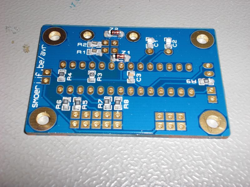
And I baked the PCB. First I measured the max temperature of the skillet and tried to get an idea of the temperature slope.

The sparkfun tutorial has some information about the temperature curve you are looking for. The skillet I had maxed out at about 220 degrees C so it worked fine.
Philips redesigns LivingColors, breaks compatibility

Philips has recently introduced a new generation of the LivingColors lamps called “LivingColors 2nd Generation“. These lamps are incompatible with existing remotes and the new remotes cannot be used with “old” lamps (as described in the manual on page 3).

This also means kits like the CC2500 Arduino shield can not control the new “LivingColors 2nd Generation”.

The exterior and user interface of the LivingColors has not been changed as far as I can see. Internally, a lot has changed.

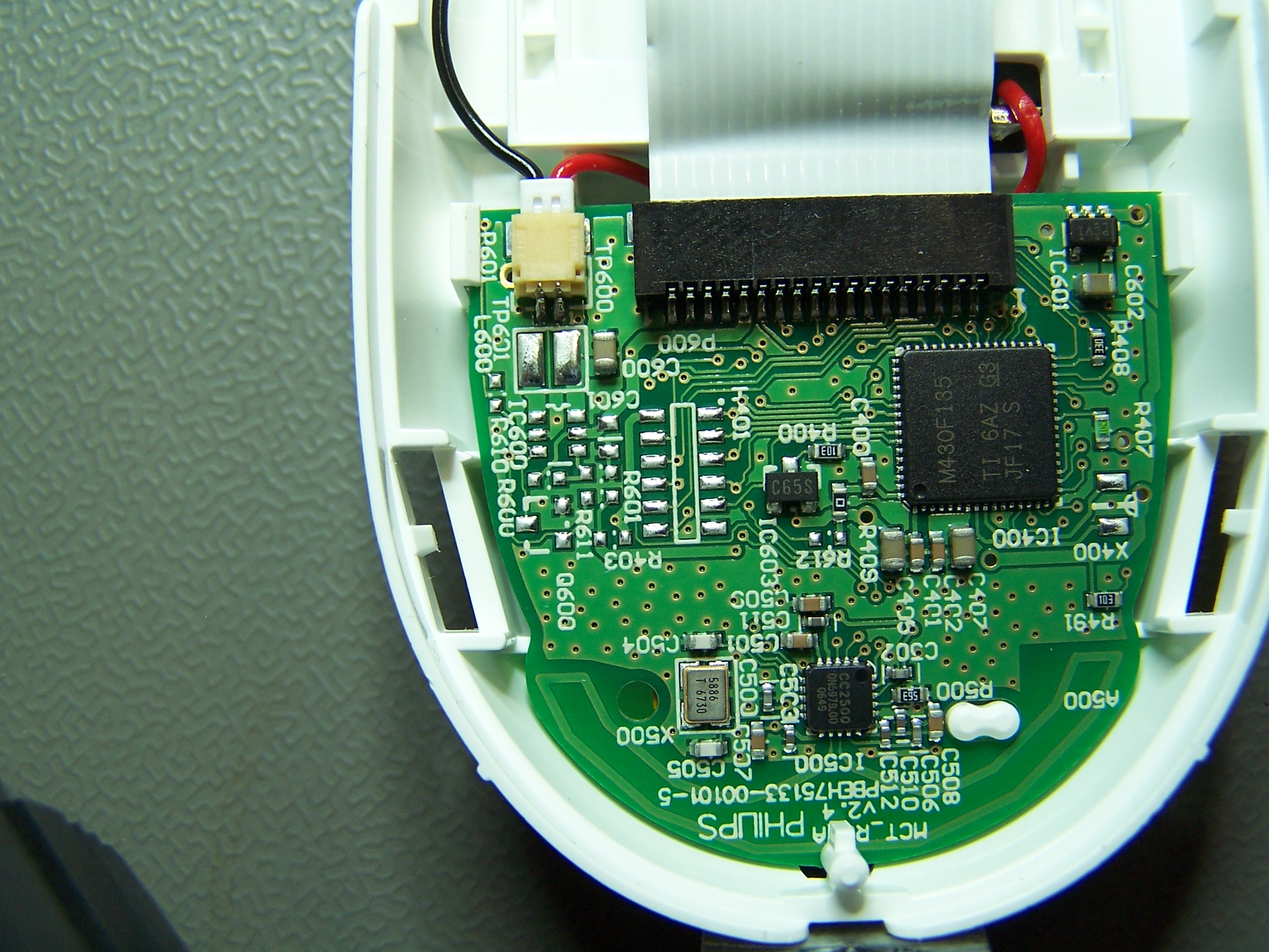
Instead of the CC2500 + MSP430 combo (shown here) :

Philips has used a CC2530 which is a 8051-alike and a IEEE 802.15.4 RF :

(you can see the PCB here)

The CC2500 and CC2530 are entirely different devices.

8 x 8 pixel RGB Display

This is a prototype for a 8 * 8 pixel RGB LED display. Multiplexing and PWM-ing should be done by the host controller.

I have it working with 8 intensities per primary color on an Arduino.

LED intensity depends on the current though the LED (the forward current I)

The problem with LED matrices is that the cheaper ones (around 9 EUR) mix LED’s from different batches with different currents (I{{sub|f}}) and intensities at the same voltage. The more expensive models (around 25 USD) use LED’s from the same batch or bin.

Here is an example of one the less expensive LED matrix :

The way around this is to use constant current drivers like the TLC5916.

<more to follow>

8 x 8 pixel red display

The 8 x 8 pixel red display is one of the first projects I did after a long hiatus. I wanted to build something useless and work on my C programming skills.

The schema was made in CadSoft Eagle, the layout was laser-printed overhead sheet and the board was etched on the kitchen. Nowadays I use MakePCB or Sparkfun‘s BatchPCB.

The schematic is really simple : a 74HCT595 as high side driver, and a 74HCT595 driving a ULN2803 as low side driver.

I kept the board simple as well so I could etch it myself.

The built up board :

The software bitbangs a couple of IO ports to control the two shift registers, intensity variation is done by changing the duty cycle of the leds. This example has 3 bits intensity (8 different intensities).  We can use these “8 pixels x 8 pixels x 3 bit” intensity as 3 bitmaps with 8 pixels x 8 pixels. The highest valued bitmap (the MSB of the intenisty) is shown 2 x als long as the second highest. The second highest value is shown 2 x as long as the LSB.

Example 2 :

Making character bitmaps is a lot of work. If you have access to a unix box of sorts you can use figlet and the 5×7 font to generate these for you.

This will result in a monospaced font which are not as pretty as the hand made fonts.

For instance, you can generate the character “0” with :

figlet -f 5x7 0 | tr ' #' '01' | sed "s/\([01]\{6\}\)/B8(\100),/"

And this will output :
B8(01000000),
B8(10100000),
B8(10100000),
B8(10100000),
B8(10100000),
B8(01000000),
B8(00000000),

I used Tom Torfs binconst macro to make the bitmaps usable.

Example 3 :